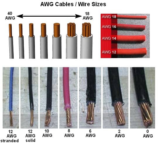
AWG is an acronym for American Wire Gauge, a specification for the diameter of conducting wires. The higher the AWG number, the thinner the wire. Category 5 cabling is usually AWG 24 wire (0.020 inch or 0.511 millimeter in diameter), while thicknet generally uses AWG 12 wire (0.080 inch or 2.050 millimeters in diameter).
The following table shows some of the various AWG gauges for different diameters of wires. Note also that the thinner the wire, the higher its electrical resistance and hence the shorter the transmission distance (because resistance varies inversely with thickness).
AWG Gauges for Various Diameters of Wires
| AWG Gauge | Diameter (inches) | Diameter (millimeters) |
| 12 | 0.080 | 2.050 |
| 14 | 0.064 | 1.630 |
| 16 | 0.051 | 1.290 |
| 18 | 0.040 | 1.020 |
| 20 | 0.032 | 0.813 |
| 22 | 0.025 | 0.643 |
| 24 | 0.020 | 0.511 |
| 30 | 0.010 | 0.254 |
There’s some background to these numbers — which may help lend some “rhyme & reason” to how they relate… and in fact will provide a means of relating one gauge to another.
- Every three gauge numbers (#20 to #23, for example) represents a division (or multiplication) of the cross-section and resistance by a factor of 2. Or, referring to the table, which lists only even-numbered gauges, AWG #20 vs. #26 would yield a factor of 4. To illustrate, #20AWG copper wire has a cross section of 1,000 circular mils (CM) and resistance/1000 ft of 10 ohms. #26 AWG, which is smaller, will have a cross section of 250 CM and resistance of 40 ohms. (All values are nominal.)
- Every 10 gauge numbers (#20 to #30AWG, for example) represents a 10-fold increase or decrease in cross section and resistance. Example: #30AWG wire is 100 CM (1/10 that of #20AWG) and 100 ohms per 1,000 feet (10 times that of #20AWG).
- As a basis for all these numbers, #10AWG copper is 1 ohm per 1,000 feet.
Having knowledge of these factors can help to simply calculate (or at least estimate) these wire parameters.
Stranded vs. Solid
Well, they are clearly different in appearance, though their purpose is the same. It stands to reason stranded construction would be more flexible. So unless you actually want stiffness — to push a wire through an opening, for example — wouldn’t stranded appear to be the better choice?
Then, too, there’s strength in numbers: rope, for example, is made of many parallel fibers — individually weak, but together quite strong. If one fiber breaks, there are many left to carry the load.
House wiring is generally solid; wiring for machine tools, automobiles, and aircraft is almost all stranded — for flexibility and redundancy in the face of vibration.
The application dictates the choice of conductor type. At high frequencies — above, say, 1,000 MHz — conductivity relies more on the surface of the conductor than its core. This is the “skin effect,” and the reason silver plating becomes important. This also applies in very high current situations — beyond that experienced in the typical aircraft situation, but occurring in major power distribution grids, for example.
The center conductors of some land-based high-power RF antenna feeds, where size and flexibility are not issues, may actually be a hollow tube — giving further evidence to the relative unimportance of the interior of the wire as a conductor in such applications.
With adequate support by the insulation — as with coaxial cable — a solid conductor will survive the vibration and yet carry an RF signal more efficiently than its stranded counterpart.