Line coding stands as a fundamental aspect of digital communications, bridging the gap between abstract binary data and its physical representation on transmission mediums. This method involves translating a digital bitstream into a form that can be easily transmitted over a wire, fiber optic cable, or even through wireless communication channels. By defining how bits are represented by voltage levels or light pulses, line coding ensures that digital information can travel reliably from one point to another, overcoming the challenges posed by noise, interference, and signal attenuation.
This article delves into the intricacies of line coding, exploring its principles, the variety of schemes used, and their applications in modern telecommunications. Through this exploration, we aim to shed light on how line coding underpins the vast networks that keep our world connected.
In this article:
- What is Line Coding?
- How is it Different from Modulation?
- What are the different types of Line Coding schemes?
- How does Line Coding affect signal bandwidth?
- How does Line Coding interact with other layers of the OSI model?
- What are the latest advancements in Line Coding technology?
- References

1. What is Line Coding?
The term “Line Coding” is used to describe a method of converting a sequence of bits into a signal that is suitable for transmission over a physical medium. It’s called “line coding” because it deals with how data is encoded onto the “line,” or the physical medium (such as copper wire, fiber optic cable, or even air in the case of wireless transmission) that carries the signal from one device to another. The “line” in this context refers to the communication channel over which the digital data is transmitted. The process specifies the relationship between the binary information in the data bitstream and the physical signal variations (such as voltage levels in electrical cables) that represent this information.
Line Coding Examples
For example, Integrated Services Digital Network (ISDN) technologies use several different line coding schemes. The U interface, which is located at the ISDN line termination point at the customer premises where a two-wire metallic cable terminates with an RJ-11 jack, uses the 2 binary, 1 quaternary (2B1Q) line coding scheme for Basic Rate Interface ISDN (BRI-ISDN) and the Bipolar with 8 Zero Substitution (B8ZS) scheme for Primary Rate Interface ISDN (PRI-ISDN) in the United States. European ISDN uses 4 binary, 3 ternary (4B3T) for BRI-ISDN and High Density Bipolar 3 (HDB3) for PRI-ISDN.
In the 2B1Q line coding scheme, a block of two binary bits can represent four different values: 00, 01, 10, and 11. These four values are mapped to one quaternary value, which is encoded using four different voltages. The first bit represents a positive or negative voltage, and the second bit represents either 1-volt or 3-volt line potential. The following table shows the four possible combinations.
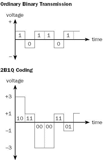
Binary Data and Corresponding Voltage Level for 2B1Q Line Coding
| Binary Data Represented | Voltage of Electrical Pulse |
| 00 | -3 |
| 01 | -1 |
| 10 | +3 |
| 11 | +1 |
The result of using 2B1Q line coding for BRI-ISDN is that a single electrical pulse represents 2 binary bits instead of 1 binary bit. This effectively doubles the possible bandwidth of the communication channel, as shown in the illustration.
2. How is it Different from Modulation?
Line coding is distinct from modulation, though they share similarities and are often used together in communication systems. The key difference lies in their primary functions and application contexts:
- Line Coding is primarily concerned with digital data representation for transmission over a physical medium. It aims to optimize the signal for the physical characteristics of the transmission medium, ensuring efficient and reliable data transfer without necessarily changing the signal’s frequency. Line coding techniques address challenges such as synchronization, bandwidth efficiency, and minimizing error rates.
- Modulation, on the other hand, involves altering a carrier signal (which can be of a higher frequency) according to the input signal (which can be the line-coded signal). Modulation can be analog or digital and is used for a variety of reasons, including to match the frequency properties of the transmission medium, to allow multiple signals to share the same medium (multiplexing), and to transmit signals over long distances by adjusting the carrier signal’s amplitude, frequency, or phase.
In essence, while line coding prepares the digital data for transmission by encoding it into a physical signal form suitable for the transmission medium, modulation further adjusts this signal to optimize the use of the medium or to achieve other specific transmission objectives. Both processes are crucial in the field of telecommunications, but they serve different roles in the preparation and transmission of data.
The term “line coding” sometimes refers to signal modulation technologies used in Digital Subscriber Line (DSL) technologies.
3. What are the different types of Line Coding schemes?
Line coding schemes are essential in digital communications for converting a stream of data bits into signals that can be transmitted over various mediums. These schemes are categorized based on how they represent binary data through signal levels or transitions. The primary types include Unipolar, Polar, Bipolar, and Manchester encoding, each with distinct characteristics and use cases.
3.1 Advantages and disadvantages of each Line Coding scheme
Unipolar Encoding
Definition: Unipolar encoding utilizes a single positive voltage level to represent binary ‘1’s and zero voltage to represent binary ‘0’s.
Advantages:
- Simplicity in implementation.
- Requires minimal power as it uses zero voltage for one of the binary states.
Disadvantages:
- Lack of a built-in mechanism for synchronization since the absence of voltage (representing ‘0’s) can be indistinguishable from a lack of signal.
- Inefficient in bandwidth utilization.
Contexts Used: It is suitable for applications where power consumption is a concern and synchronization can be managed externally.
Polar Encoding
Definition: Polar encoding uses two different voltage levels, one positive and one negative, to represent binary ‘1’s and ‘0’s.
Advantages:
- Better error detection capabilities due to the distinct representation of binary states.
- More efficient in terms of synchronization compared to unipolar.
Disadvantages:
- Requires bipolar power supply.
- Still susceptible to baseline wander and DC component issues.
Contexts Used: Employed in environments where error detection and synchronization are important but where the system can manage the DC component.
Bipolar Encoding
Definition: Bipolar encoding alternates the polarity of voltage levels for each ‘1’ bit, while ‘0’ bits are represented by zero voltage.
Advantages:
- Reduces the likelihood of synchronization errors by ensuring frequent line voltage changes.
- Minimizes the DC component, making it suitable for long-distance transmission.
Disadvantages:
- More complex circuitry required for encoding and decoding.
- Zero voltage for ‘0’s can still lead to synchronization issues if long sequences of zeros occur.
Contexts Used: Ideal for systems where minimizing the DC component and improving error detection are critical, such as in T1 and E1 carrier systems.
Manchester Encoding
Definition: Manchester encoding represents bits through transitions. A transition from high to low represents one binary state, and a transition from low to high represents the other.
Advantages:
- Inherent synchronization capability due to constant transitions.
- Eliminates the DC component entirely.
Disadvantages:
- Effectively halves the bandwidth by requiring transitions within each bit period.
- More complex implementation compared to simpler schemes.
Contexts Used: Widely used in Ethernet networks and RFID technologies where synchronization and the absence of a DC component are paramount.
3.2 How to choose the right Line Coding scheme for a specific application
Selecting an appropriate line coding technique involves considering several factors:
- Transmission Medium: Optical fiber, copper cables, and wireless channels each have unique characteristics. For instance, optical systems may prefer Manchester encoding due to its synchronization capabilities, whereas long-distance copper transmissions might benefit from bipolar encoding to minimize the DC component.
- Data Rate: Higher data rates may require more sophisticated encoding schemes like Manchester to maintain synchronization, especially in environments with a high bit error rate.
- Environmental Conditions: Electromagnetic interference (EMI) can affect signal integrity. Polar or bipolar schemes with distinct voltage levels can offer better resilience against EMI compared to unipolar schemes.
- Power Consumption: For battery-operated devices or low-power applications, unipolar encoding might be preferred due to its lower power requirements.
- System Complexity and Cost: Simpler schemes like unipolar and polar encoding are easier and cheaper to implement but may not offer the benefits of more complex schemes like Manchester or bipolar encoding in terms of synchronization and bandwidth efficiency.
In conclusion, the choice of line coding scheme is critical and should be made by carefully balancing these factors against the requirements of the specific application. Understanding the advantages and disadvantages of each scheme allows network designers and engineers to tailor their systems for optimal performance, reliability, and cost-efficiency.
4. How does Line Coding affect signal bandwidth?
Line coding significantly impacts the bandwidth of a signal transmitted over a communication channel. The choice of line coding scheme determines the frequency spectrum of the encoded signal and, consequently, the bandwidth it occupies. Unipolar schemes, where signal levels are all positive or all negative, tend to be simpler but can require more bandwidth for a given data rate compared to polar schemes, where signals alternate between positive and negative values. Bipolar schemes, including Alternate Mark Inversion (AMI), use three levels (positive, zero, negative) and are more efficient in bandwidth utilization but can be more complex to implement.
Manchester encoding, a form of polar encoding, ensures that each bit has a transition, facilitating clock recovery but at the cost of doubling the bandwidth of the baseband signal. The choice of line coding scheme directly influences the trade-offs between bandwidth efficiency, complexity, error detection capabilities, and resilience to noise and interference.
5. How does Line Coding interact with other layers of the OSI model?
Line coding is primarily a concern of the Physical Layer (Layer 1) of the OSI model, which deals with the transmission of raw bit streams over a physical medium. However, its effects ripple upward through the OSI layers. For instance, the Data Link Layer (Layer 2) may need to account for the characteristics of the line-coded signal when designing frame structures or when implementing error detection and correction algorithms. The efficiency and reliability of line coding can influence network performance metrics such as throughput and latency, which are relevant to higher layers, including the Transport (Layer 4) and Application Layers (Layer 7). While line coding itself does not directly interact with higher layers, the quality and characteristics of the physical layer transmission have a foundational impact on the overall network architecture and performance.
6. What are the latest advancements in Line Coding technology?
Recent advancements in line coding technology focus on increasing data rates, enhancing signal integrity over longer distances, and improving spectral efficiency for both wired and wireless communications. Techniques such as 4B/5B, 8B/10B, and 64B/66B encoding have been developed to provide a good balance between bandwidth efficiency and reliable transmission, especially in high-speed networks like Ethernet and optical fiber communications. Forward Error Correction (FEC) codes are increasingly integrated with line coding schemes to improve error resilience without significantly increasing bandwidth requirements.
In optical communications, advanced modulation formats, including Pulse Amplitude Modulation (PAM-4), Quadrature Amplitude Modulation (QAM), and Differential Phase Shift Keying (DPSK), represent the forefront of line coding, enabling multi-terabit per second transmission capacities. Research continues into machine learning and AI algorithms to optimize line coding schemes dynamically based on real-time channel conditions, aiming to maximize data rates while minimizing errors and power consumption.
7. References
- Books:
- “Digital Communications” by John Proakis and Masoud Salehi.
- “Data and Computer Communications” by William Stallings.
- RFCs: