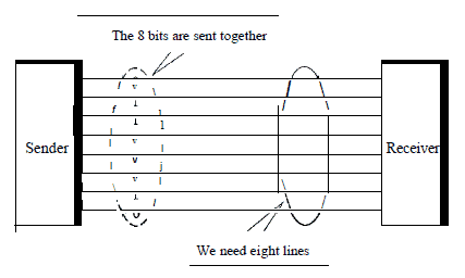
Parallel Transmission is a form of signal transmission that sends information 8 or more bits at a time over a cable. Parallel interfaces are used mainly to connect printers, hard drives, and other peripherals to computers.
How It Works
The difference between serial and parallel transmission
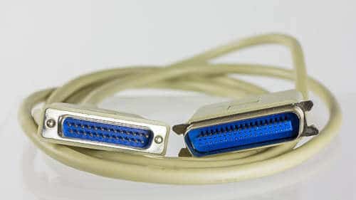
While a serial interface such as RS-232 transfers only 1 bit of data at a time, parallel interfaces typically transfer 8 bits (1 byte) of data at a time. A typical parallel interface for a computer uses a port that accepts a female DB25 connector. The parallel interface for a printer often uses a 36-pin Centronics connector.
For the DB25 connector, all 25 of the leads must be working for parallel transmission to function. In contrast, serial interfaces, which sometimes use DB25 connectors, require only three active leads to transmit data. The parallel 25-pin connector has 17 leads for carrying signals and 8 leads for grounding. Of the 17 leads, 8 are used for data bit signals, 5 for status signals, and 4 for handshaking.
Typical throughput of a parallel interface is 16 KBps or 128 Kbps. Parallel communication (parallel transmission) is usually limited to cables of up to 6 meters, but devices can be used to boost signals for longer distances.
Other questions we may want to know the answers to
IEEE 1284 standard
IEEE 1284 is a standard for parallel transmission that defines bi-directional parallel communications between computers and other devices. It was originally developed in the 1970s by Centronics and was widely known as the Centronics port, both before and after its IEEE standardization.
Centronics standard or Compatibility Mode (SPP)
Centronics standard is a uni-directional implementation with only a few differences from the original Centronics design. This mode is almost exclusively used for printers. The only signals that the printer can send back to the host are some fixed-meaning status lines that signal common error conditions, such as the printer running out of paper.
Enhanced Parallel Port (EPP)
Enhanced Parallel Port is a half-duplex bi-directional interface designed to allow devices like printers, scanners, or storage devices to transmit large amounts of data while quickly being able to switch channel direction. EPP can provide up to 2 MByte/s bandwidth, approximately 15 times the speed achieved with normal parallel-port communication with far less CPU overhead.
Extended Capability Port (ECP)
Extended Capability Port is a half-duplex bi-directional interface similar to EPP, except that PC implementations use direct memory access (usually ISA DMA on channel 3) to provide even faster data transfer than EPP by having the ISA DMA hardware and the parallel port interface hardware handle the work of transferring the data instead of letting the CPU do this work. Many devices that interface using this mode support RLE compression. ECP can provide up to 2.5 MByte/s of bandwidth, which is the natural limit of 8-bit ISA DMA.[3] An ECP interface on a PC can improve transfers to pre-IEEE-1284 printers as well, by reducing the CPU load during the transfer; however, the transfer, in that case, is unidirectional.
Cables and Connectors
The IEEE defined three types of connectors and six types of cables. The type A connector is the parallel port connector (Sub-D25) found on most computers. The type B connector is what is usually called the Centronics connector. And there is a new connector that is called MDR36 and which is called type C. The pinning for the Centronics and Sub-D25 is not changed.
The different cables that are defined are:
| AMAM | Type A male to type A male |
|---|---|
| AMAF | Type A male to type A female |
| AB | Type A male to type B |
| AC | Type A male to type C |
| BC | Type B male to type C |
| CC | Type C male to type C |
Also, the cable characteristics are defined:
- The cable shield must be connected to the connector back shell using a 360° concentric method
- The shield must be minimal 85 % optical braid coverage over foil
- The maximum crosstalk is not greater then 10 %
- All signals are send over a twisted pair with their signal ground return
- Each pair must have an impedance of 62 ± 6 ohms @ 4 to 16 MHz
Pinning Sub-D25 A-connector
| Pin | Signal | Abbr. | Source |
|---|---|---|---|
| 1 | Data Strobe (low) | STROBE | Computer |
| 2 | Data Bit 1 (LSB) | D1 | Computer |
| 3 | Data Bit 2 | D2 | Computer |
| 4 | Data Bit 3 | D3 | Computer |
| 5 | Data Bit 4 | D4 | Computer |
| 6 | Data Bit 5 | D5 | Computer |
| 7 | Data Bit 6 | D6 | Computer |
| 8 | Data Bit 7 | D7 | Computer |
| 9 | Data Bit 8 (LSB) | D8 | Computer |
| 10 | Acknowledge (low) | ACK | Printer |
| 11 | Busy (high) | BUSY | Printer |
| 12 | Paper End (high) | PE | Printer |
| 13 | Select (high) | SEL | Printer |
| 14 | Auto Line Feed (low) | LF | Computer |
| 15 | Error (low) | ERROR | Printer |
| 16 | Initialize Printer (prime-low) | PRIME | Computer |
| 17 | Select Input (low) | SEL | Computer |
| 18 | Return/ground | GND | – |
| 19 | Return/ground | GND | – |
| 20 | Return/ground | GND | – |
| 21 | Return/ground | GND | – |
| 22 | Return/ground | GND | – |
| 23 | Return/ground | GND | – |
| 24 | Return/ground | GND | – |
| 25 | Return/ground | GND | – |
Pin 1 carries the strobe signal. It maintains a level of between 2.8 and 5 volts, but drops below 0.5 volts whenever the computer sends a byte of data. This drop in voltage tells the printer that data is being sent.
Pins 2 through 9 are used to carry data. To indicate that a bit has a value of 1, a charge of 5 volts is sent through the correct pin. No charge on a pin indicates a value of 0. This is a simple but highly effective way to transmit digital information over an analog cable in real-time.
Pin 10 sends the acknowledge signal from the printer to the computer. Like Pin 1, it maintains a charge and drops the voltage below 0.5 volts to let the computer know that the data was received.
If the printer is busy, it will charge Pin 11. Then, it will drop the voltage below 0.5 volts to let the computer know it is ready to receive more data.
The printer lets the computer know if it is out of paper by sending a charge on Pin 12.
As long as the computer is receiving a charge on Pin 13, it knows that the device is online.
The computer sends an auto feed signal to the printer through Pin 14 using a 5-volt charge.
If the printer has any problems, it drops the voltage to less than 0.5 volts on Pin 15 to let the computer know that there is an error.
Whenever a new print job is ready, the computer drops the charge on Pin 16 to initialize the printer.
Pin 17 is used by the computer to remotely take the printer offline. This is accomplished by sending a charge to the printer and maintaining it as long as you want the printer offline.
Pins 18-25 are grounds and are used as a reference signal for the low (below 0.5 volts) charge.
Pinning MDR 36 pins C-connector
| Pin | Signal | Abbr. | Source |
|---|---|---|---|
| 1 | Busy (high) | BUSY | Printer |
| 2 | Select (active high) | SEL | Printer |
| 3 | Acknowledge (active low) | ACK | Printer |
| 4 | Error (Fault- active low) | ERROR | Printer |
| 5 | Paper Error (active high | PE | Printer |
| 6 | Data Bit 0 (LSB) | D0 | Computer |
| 7 | Data Bit 1 | D1 | Computer/Printer |
| 8 | Data Bit 2 | D2 | Computer/Printer |
| 9 | Data Bit 3 | D3 | Computer/Printer |
| 10 | Data Bit 4 | D4 | Computer/Printer |
| 11 | Data Bit 5 | D5 | Computer/Printer |
| 12 | Data Bit 6 | D6 | Computer/Printer |
| 13 | Data Bit 7 (MSB) | D7 | Computer/Printer |
| 14 | Initial | INIT | |
| 15 | Data Strobe (low) | STROBE | Computer |
| 16 | Select Input (active low) | SI | |
| 17 | Auto Line Feed (active low) | ALF | |
| 18 | Host Logic High | HLH | Computer |
| 19 | Return/Ground | RGND | |
| 20 | Return/Ground | RGND | |
| 21 | Return/Ground | RGND | |
| 22 | Return/Ground | RGND | |
| 23 | Return/Ground | RGND | |
| 24 | Return/Ground | RGND | |
| 25 | Return/Ground | RGND | |
| 26 | Return/Ground | RGND | |
| 27 | Return/Ground | RGND | |
| 28 | Return/Ground | RGND | |
| 29 | Return/Ground | RGND | |
| 30 | Return/Ground | RGND | |
| 31 | Return/Ground | RGND | |
| 32 | Return/Ground | RGND | |
| 33 | Return/Ground | RGND | |
| 34 | Return/Ground | RGND | |
| 35 | Return/Ground | RGND | |
| 36 | Peripheral Logic High | PLH | Printer |
Functional Description
| STROBE | Active low pulse used to transfer data into the printer. | Pulse with must be between 0.5 and 500 microseconds for most printers. |
| ACK | Active low pulse indicates that data has been received and the printer is ready to accept more. | |
| BUSY | A high signal indicates that the printer cannot receive data. | |
| PE | A high signal indicates that the printer is out of paper (Paper End) | |
| SELECT OUT | A high signal indicates that the printer is on-line | |
| AUTO FEED | A low signal indicates to the printer that a line feed is required after each Carriage return. | This signal is used as a ground line by some manufacturers. |
| OSCXT | A 100-200 KHz signal used by true Centronics printers only. | |
| +5V | +5Vdc | Not provided by all manufacturers |
| PRIME | A low signal resets the printer to its power-up state and the printer buffer is cleared | |
| FAULT | A low signal indicates that the printer is in an off-line or error state | |
| LINE COUNT | Used by true Centronics printers only. | Most of the time not used |
| LINE COUNT | See 34 | |
| SELECT IN | A high signal indicates to the printer that a DC1/ DC3 code is valid. | This signal is used by a few manufacturers |
| Host Logic High | A high signal indicates that the host is alive (turned on). | Specific IEEE 1284 signal. |
| Peripheral Logic High | A high signal indicates that the peripheral (printer) is alive (turned on). | Specific IEEE 1284 signal. |